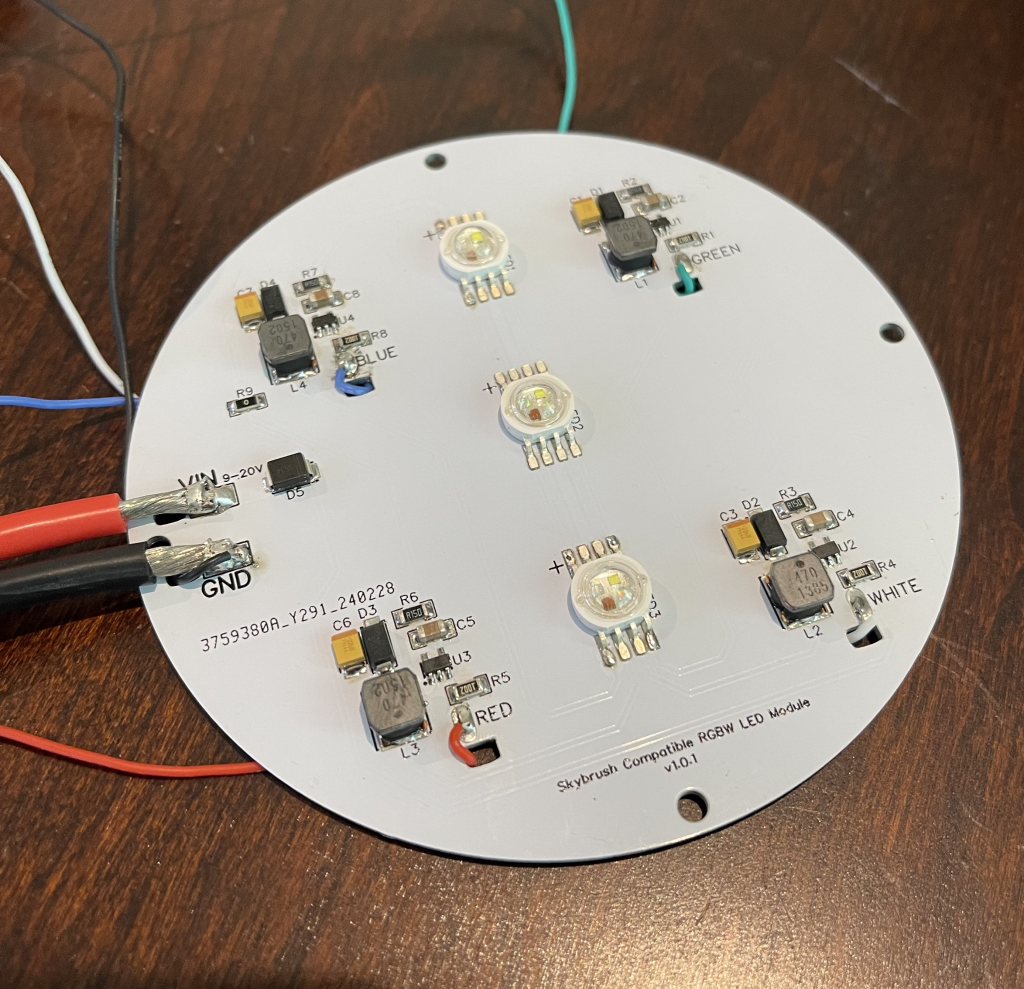
After having issues with the Neopixel LED modules on the two newer drones (a blog post about that headache is coming soon…), I decided to try a different design by Techventures Sean for an LED module based on the use case of Skybrush drones.
Heads up, this post is part of a more extensive series about building drones for a small drone show. This post is part six of the series, and previously, I covered 3D designing mounts for the LED modules from Adafruit.
I mentioned two separate LED module designs in the first paragraph. But what are these two options?
The option we have currently implemented is the 4W LEDs from Adafruit. These are cheap and offer a plug-and-play way to light up the sky. They also work under the NeoPixel branding, so documentation is extensive. I covered that setup in this post:
The second option is what I’ll be covering in this post. Sean, the creator of this design, recommended it to me on the Skybrush Discord when I expressed frustration with some problems with the Neopixel LEDs.
-Sean (Mwd-Sean)“That module is the equivalent to 8-10 of those Adafruit modules.”
The design for the light module comprises four main controlling components, BGRW (as shown in the animation below. Each part is individually controlled via 4 PWM signals from the flight controller addressing each light color:

Sean’s RGBW LED Module https://oshwlab.com/sean1/skybrush-rgbw-led
After reviewing most diagrams and parts and looking at what tools I need for assembly, I ordered all the necessary parts from JLCPCB (which manufactures PCBs), LCSC Parts (which manufactures the elements, like resistors and capacitors), and the LED chips themselves from Amazon. Shipping took about a week to arrive.
img: Sean (TechVentures)

I began attempting to solder the first parts onto the PCB when it became more apparent how unprepared I was. One obstacle was the solder itself. I installed my TS101 soldering iron with a small tip, but the solder wasn’t flowing well, and flux made a mess of it.

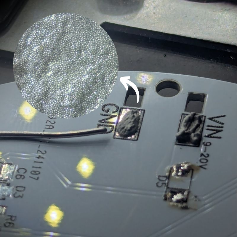
I ordered a similar but thinner version of the solder I’d been using called Solder Paste. Solder paste comprises primarily micro solder beads, which, mixed with a flux-like liquid, lowers the melting temperature to about 180c instead of the 250c I had been accustomed to. 1
img: Solder paste on PCB, with a closeup taken under the microscope.
With the soldering down and the assistance of a microscope, I could nail down the assembly: placing the components and eventually soldering them into place. Although the first attempt did come with its problems, more minor mistakes mostly – not being patient and forgiving when I misplaced a component. Remember how much solder paste needs to be pre-applied.
Also, realizing I made a small ordering mistake in the number of specific components I needed to place on the PCB, I am currently waiting for that order to complete the assembly.
- Unfortunately, the PCB is designed with heat dissipation in mind. It is made almost entirely of aluminum, making it more challenging to get the solder to the required melting temperature. ↩︎

Leave a Reply